RISA-2D has design databases for wood shear walls and diaphragms which are used to optimize the nailing and hold downs for the wall. The criteria used for this optimization is specified on the Wood Wall (Fasteners) and Wood Diaphragms tabs of the Design Rules spreadsheet. In addition to this basic criteria, the user may specify a subset of the overall database from which the design / optimization must be performed.
Each database of hold downs is specified by an XML file in the "Hold Downs" sub-directory of the Wood Wall panels directory. The location of this directory is based on the information in the File Locations tab of the Tools - Application Settings dialog.
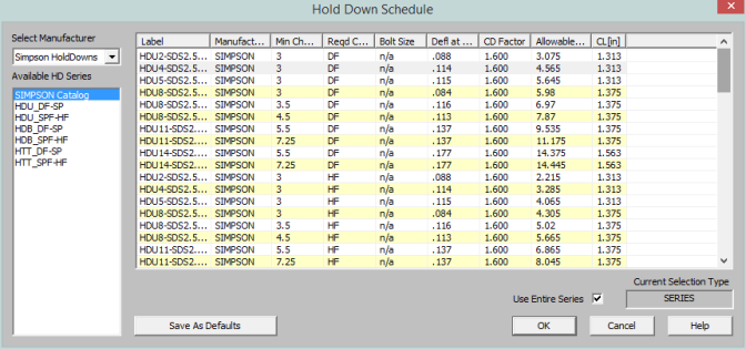
The program comes pre-loaded with three XML files, one for Simpson hold-downs, one for Canadian Simpson hold-downs, and one for USP hold-downs. The name of the XML file itself will be used in the list of databases in the Hold Down Schedule Dialog.
The first sheet of the XML file should always be descriptive of the contents of the database (such as Simpson HoldDowns). This is because the name used here is the name used in the Design Rules spreadsheet. This sheet contains all of the identifier, design and code check information used for each hold down. These entries are described below.
The following fields are required information. If they are not provided or are left blank, then that hold down will not be available for use in that database.
The Label field is used to identify the hold down. This field must be referenced on the sheets that identify families or groups of hold downs. Maximum numbers of characters for this field is 32.
The Deflection at Peak Load entry is used to calculate the deflection of the shear wall per APA / NDS formulas. This deflection is then reported on the shear wall detail report for each wall panel.
The CD Factor is the assumed load duration factor that was used as the basis for specifying the listed Allowable Tension value for that hold down.
A load combination may be solved with a load duration factor different from the CD Factor described above. When this is the case, the Allowable Tension for that hold down will be adjusted based on the difference between the assumed and actual load duration factors.
The following fields are optional. They are not currently used in the design or capacity calculations, but are reported on the detail reports for reference purposes only.
The Manufacturer field is an identifier for the hold down. It is provided so that the engineer can more easily identify the callouts for their final design drawings.
The allowable capacity of the hold down will vary based on the Chord Thickness. Therefore, the Min Chord Thickness gives the minimum chord thickness that will yield the listed allowable tension load. However, this field is NOT currently used in the calculations. A future revision may provide a warning message if the actual chord thickness provided is less than required.
The allowable capacity of the hold down will vary based on the density of the wood species being used. Therefore, the Required Chord Species lists the density assumed for the entered allowable tension. However, this field is NOT currently checked in the calculations. A future revision may provide a warning message if the actual chord density provided is less than required.
The Bolt Size when specified is used to reduce the axial capacity of the hold down chord itself. The only change to the calculation is that the program will perform the allowable tension check on the net area of the chord member rather than the gross area.
The other sheets allow the user to group hold downs together into families for optimization purposes. These additional sheets CANNOT be the first sheet in the XML file as that first sheet must always be the one where the full database information resides.
The hold down labels specified on these sheets refer only to hold downs that have already been defined on the full database sheet. The information in this sheet need not be organized in a specific order. Instead, they will always be optimized based on the assumption that the hold down cost is directly related to the tension capacity. Therefore, when this group is selected, then the hold down within the group with the code check closest to unity, but still less than 1.0 will get selected during the optimization process.
Each database of straps is specified by an XML file in the "Straps" sub-directory of the Wood Wall panels directory. The location of this directory is based on the information in the File Locations tab of the Tools - Application Settings dialog.
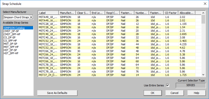
The program comes pre-loaded with a database for Simpson Chord Straps. The name of the XML file itself will be used in the list of databases in the Strap Schedule Dialog.
The first sheet of the XML file should always be descriptive of the contents of the database (such as Simpson Chord Straps). This is because the name used here is the name used in the Design Rules spreadsheet. This sheet contains all of the identifier, design and code check information used for each strap. These entries are described below.
The following fields are required information. If they are not provided or are left blank, then that strap will not be available for use in that database.
The Label field is used to identify the strap. This field must be referenced on the sheets that identify families or groups of straps. Maximum numbers of characters for this field is 32.
The CD Factor is the assumed load duration factor that was used as the basis for specifying the listed Allowable Tension value for that hold down.
A load combination may be solved with a load duration factor different from the CD Factor described above. When this is the case, the Allowable Tension for that hold down will be adjusted based on the difference between the assumed and actual load duration factors.
Allowable Tension is the value the program will use when designing the strap to be used.
The following fields are optional. They are not currently used in the design or capacity calculations, but are reported on the detail reports for reference purposes only.
The Manufacturer field is an identifier for the strap. It is provided so that the engineer can more easily identify the callouts for their final design drawings.
The Clear Span is the distance the strap is required to span between elements it is resisting the tension of.
End Length is the length of the strap that extends past the clear span
The allowable capacity of the strap will vary based on the density of the wood species being used. Therefore, the Required Chord Species lists the density assumed for the entered allowable tension. However, this field is NOT currently checked in the calculations. A future revision may provide a warning message if the actual chord density provided is less than required.
The Fastener Type shows whether Nails or Bolts is used to fasten the strap to the tension chords.
The Number of Fasteners field show how many fasteners are required to be used to meet the requirements of the tension capacity given by the strap.
The other sheets allow the user to group straps together into families for optimization purposes. These additional sheets CANNOT be the first sheet in the XML file as that first sheet must always be the one where the full database information resides.
The strap labels specified on these sheets refer only to straps that have already been defined on the full database sheet. The information in this sheet need not be organized in a specific order. Instead, they will always be optimized based on the assumption that thestrap cost is directly related to the tension capacity. Therefore, when this group is selected, then the strap within the group with the code check closest to unity, but still less than 1.0 will get selected during the optimization process.
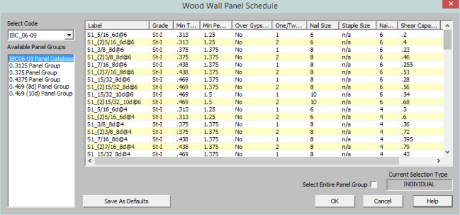
Each database of wall panels is specified by an XML file in the "Shear Panels" sub-directory of the Wood Wall panels directory. This directory is located based on the information File Locations tab of the Tools - Application Settings dialog.
The program comes preloaded with XML files, including OSB and Plywood databases from the American Wood Council's 2015 Special Design Provisions for Wind and Seismic.
Note:
The first sheet of the XML file should always be descriptive of the contents of the database (such as IBC 2012). This is because the name used here is the name used in the Design Rules spreadsheet. This sheet contains all of the identifier, nailing, design and code check information for each nailing schedule. These entries are described below.
The following fields are required information. If they are not provided or are left blank, then that nailing schedule will not be available for use in the database.
The Label field is a used to identify the panel schedule and its nailing requirements. This field must be referenced on the sheets that identify families or groups of panels. Maximum numbers of characters for this field is 32.
Note:
The Min Panel Thickness is used during the design optimization to limit the selected panels based on the Design Rules chosen by the user. It is also used to help set the elastic stiffness of the wall panel used during the FEM solution.
The Ga value is the Apparent Shear Stiffness from nail slip and panel deformation as defined in equation 4.3-1 of the NDS' Special Design Provisions for Wind and Seismic. This value (in combination with the Min Panel Thickness defined above) is used to set the elastic stiffness of the wall panel that will be used during the FEM solution.
Note:
The One/Two Sided field is used during the design optimization to limit the available panels based on the Design Rules specified by the user.
The Boundary Nail Spacing field is used during the design optimization to limit the available panels based on the Design Rules specified by the user.
Note:
The Shear Capacity listed in the spreadsheet is the primary value that controls the code checking of the shear wall. This is the seismic capacity, which the program can automatically increase for wind loads if the Wind ASIF function is enabled.
The following fields are optional. They are not currently used in the design or capacity calculations, but are reported on the detail reports for informational purposes only.
The Panel Grade and Min Penetration fields are identifiers for the engineer, but are not used in the design calculations. They are provided so that the engineer can most easily identify the panels in their design results and drawings.
The Panel Applied Over Gypsum field is also a identifier for the engineer that will not be used in the design calculations.
The Nail Size listed in the spreadsheet is intended to refer to the Common nail size, but is reported only for reference purposes and are NOT used in the capacity calculations. If the nail size is changed by the user, then the user should also change the Shear Capacity entry accordingly. Below is a reference table for common, box, and sinker nails.
The Staple size listed in the database is reported for reference purposes only. If the staple size is entered or changed by the user, then the user should also change the shear capacity entry to the appropriate value.
The other sheets in the database allow the user to organize multiple nailing schedules into groups or families for design optimization purposes. These additional sheets CANNOT be the first sheet in the XML file as that first sheet must always be the one where the full database information resides.
The panel labels specified on these sheets refer only to panel / nailing schedules that have already been defined on the full database sheet. The information in this sheet need not be organized in a specific order. Instead, they will always be optimized based on the assumption that the installed cost is directly related to the shear capacity. Therefore, when a group or family is selected, then the nailing schedule within the group with the code check closest to unity, but still less than 1.0 will get selected during the optimization process.